
Pico-and femto-second laser micro-machining for surface texturing

Tatsuhiko Aizawa; Surface Engineering Design Laboratory, Shibaura Institute of Technology; Tokyo 144-0065, Japan; taizawa@sic.shibaura-it.ac.jp
Tadahiko Inohara; LPS Works, Co. Ltd., Tokyo 144-0033, Japan; inohara@lps-works.com
Abstract
The pico-and femto-second laser micro-machining has grown up as a reliable tool for precise manufacturing and electronic industries to make fine drilling and machining into hard metals and ceramics as well as soft plastic and to form various nano- and micro-textures for improvement of surface functions and properties in products. The ultrashort-pulse laser machining systems were developed to describe the fine micro-drilling and micro-texturing behavior for various materials. Accuracy in circularity and drilled depth were evaluated to discuss the effect of substrate materials on the laser micro-drilling. Accuracy in unit geometry and alignment was also discussed for applications. A carbon base mold substrate was micro-machined to transcribe its microtextures to transparent plastics and oxide glasses. Three practical examples were introduced to demonstrate the effectiveness of nano-/micro-texturing on the improvement of micro-joinability, the reduction in friction and wear of mechanical parts and tools, and the surface property control. The fast-rate laser machinability, the spatial resolution in laser micro-texturing as well as the laser micromanufacturing capacity were discussed to aim at the future innovations in manufacturing toward the sustainable society.
Keywords: Pico-second laser micro-machining, Femto-second laser micromachining, Micro-drilling, Micro-texturing, Nano-/micro-texturing, Laser micropatterning
1. Introduction
The laser technology for manufacturing is classified into two categories; e.g., thermal and athermal processings [1]. CO2-laser with continuous power supply and fiber-lasers with use of short pulses are typical processing for welding, machining and joining by formation of thermally hot spots [2]. Various fiber lasers [3] have been developed and applied to laser welding, laser machining, laser marking and so on [3]. Most of them utilize the nano-second solid-state oscillators and make thermal machining of materials. In recent, pico- and femtosecond laser machining [4-6] is widely utilized for athermal removal of materials with high dimensional accuracy in practice.
There are two keywords to classify the laser processing; i.e., the wave length of light and the pulse duration time. CO2 laser has the longest wave length of 10.6µm while excimer laser by KrF, 248 nm. Most of laser wave length (λ) ranges from the far ultra-violet regime less than 200 nm to infra-red regime more than 20µm. Since every material has its own relaxation rime (τ0), most of laser power can be absorbed by the material having the equivalentτ0 to λ. Then, this targeting work material is athermally machined by selecting the laser with suitable wave length; otherwise, the work is only thermally cut or drilled. A micro-machining essentially requires for fast-rate removal of materials with sufficient accuracy in dimension and geometry; the repetition frequency as well as the wave length must be optimally selected to make suitable laser micromachining to each work-material. With use of SHG (Second Harmonic Generator), THG (Third Harmonic Generator) and FHG (Forth Harmonic Generator), the fundamental wave length of 1064 nm is controllable to be 532 nm, 355 nm and 266 nm, respectively.
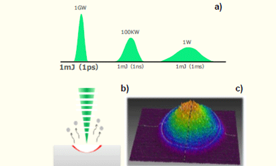
The pulse duration time (Δt) is important for short-pulse laser micromachining. As shown in Fig. 1 a), the pulse power increases significantly with reduction of Δt. When the laser energy with Δt = 1 ms is 1mJ, the laser power (P) is only 1W; P reaches to 1 GW only by shortening Δt down to 1 ps.
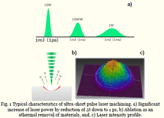
Under high power laser irradiation, most of materials is athermally removed, or, ablazed, as depicted in Fig. 1 b). The dimensional accuracy in laser micromachining is determined by focusing the laser spot for this ablation process. This laser irradiation has a finite spot size which is dependent on λ and Δt. The laser intensity distributes even in the focused spot; e.g., the well-controlled laser intensity distributes in Gaussian profile as depicted in Fig. 1 c).
In the following, our developing ultrashort pulse laser machining systems are employed to make micro-drilling and micro-texturing into various kinds of work materials. In particular, the laser micro-texturing technology is applied to microjoining process of dissimilar polymers, and, to micro-dimple formation for friction control of sliding parts and components and for reservoir of wear debris during dry cutting. Further applications including the surface property control by using the nano-/micro-texturing are discussed in this chapter.
2. Pico- and femto-second laser micro-machining system
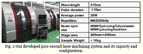
Our developed pico- and femto-second laser machining systems are stated
with some comments on their capacity and configuration.
Pico-second laser micro-machining system. A single pico-second is equivalent to the relaxation time of molecular bonding stage; its pulsed power is readily absorbed by most of work materials. Three types of pico-second laser machining systems were developed; a standard system and its configuration are shown in Fig. 2. The machining speed is dependent on the repletion frequency and average power. The dimensional accuracy in machining is determined by the beam spot size. To be discussed later, this spot size depends on the optical system; e.g., the minimum spot size can be controlled down to 1µm when every lens is fixed on the stage. However, when the lens position is controlled during machining, the spot size becomes wider; e.g., it is limited by 10µm when using the galvanometer.
Femto-second laser micro-machining system. A single femto-second or sub-pico-second lasers are developed for innovative research and
development; most industrial applications stand on this laser machining in the order of 100 femto-seconds. Our developed system and its onfiguration is shown in Fig. 3.
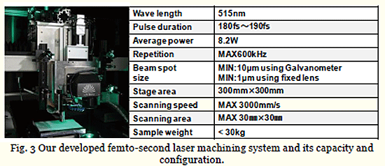
Since the focused spot of work materials is subjected to ultra-high power irradiation, how to scan the beam spot becomes more important when using this laser machining system. Higher repetition frequency of laser beams as well as higher scanning speed result in fast-rate, dimensionally accurate machining. At present, a laser oscillator with the repetition frequency of 40 MHs has been already developed for machining. How to make fast control this short pulse laser becomes an essential issue in laser machining design.
Optical unit control. In parallel with the development of laser oscillators and machining unit, the optical unit design is also important for accurate laser machining. Two unit designs are introduced in Fig. 4; e.g., an optical control unit with use of galvanometer to distribute the laser beam as designed, and, a beam rotator for laser drilling with accurate circularity. The former unit is a standard approach for laser machining with moderate rate; new controller must be developed to make much faster-rate laser machining. The latter is a powerful tool to rotate the optical units and to move the laser beam in the axisymmetric manner.
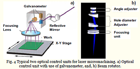
Various controlling tools of laser beam can be designed and developed for each application of laser machining.
3. Fine micro-drilling into metallic alloys and ceramics
These pico- and femto-seconds with the pulse duration in the order of 10-12 s and 10-15 s, provide a reliable means to drill the through-holes into the ceramics, the metallic alloys and the plastics [7]. Compared to the micro-milling and the micro-EDM (Electrical Discharge Machining), finer through-holes with higher circularity are formed without residuals at the inlet of holes and without deterioration on their inner surfaces [8]. In addition, no micro-milling tools and no thin EDM wires are needed to drill the lots of through holes onto the relatively large area. In this laser drilling process, the surface quality of through holes as well as their circularity are strongly dependent on the laser beam control, as summarized in [9]. In the conventional fiber-laser machining, the inlet of through holes is deteriorated by the redeposits and the residuals [10]. Even when using the pico-second pulse lasers, the through-hole shape is also damaged by the unstable laser beams [11, 12]. Typical damage of through-holes comes from the branching from the straight hole drilled in the initial stage to two holes. The deviation of beam focusing and positioning directly induces these defects [7-8,13]. Our developed pico-second laser machining system for industrial applications is applied to drill the through-holes into the ceramic plates. The beam rotator is used as a trepanning system for laser drilling. The alumina plate with the thickness of 1mm is employed as a substrate. SEM (scanning electron microscopy) is used to measure the diameter of through-holes as well as their aspect ratio. The replica method is also utilized to describe the geometric alignment and homogeneity of through-holes. The drilled through-holes with the uniform diameter of 50µm and the aspect ratio of 10.0, are accurately aligned into the alumina plate. The present trepanning device works to control the diameter of irradiation for fine drilling of the tapered and inversely tapered through-holes into steels.
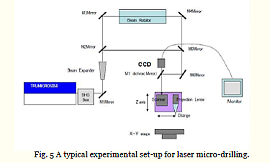
Micro-drilling into ceramic substrates. The alumina plate is prepared for the laser drilling under the experimental setup in Fig. 5. The beam rotator as well as projection lens unit are utilized to improve the focused beam quality. Through the CCD and display, the micro-drilling process is monitored during operation.
 Let us first evaluate on the difference of drilling behavior between the fiber lasers and the pico-second laser. The through-hole with the diameter of 50µm is drilled into alumina plate. When using the normal fiber lasers, the surroundings of hole are completely damaged with deposits on them I Fig. 6 a). While, the accurate hole with circularity of 1µm is drilled by the pico-second laser without damage and deposits, as shown in Fig. 6 b).
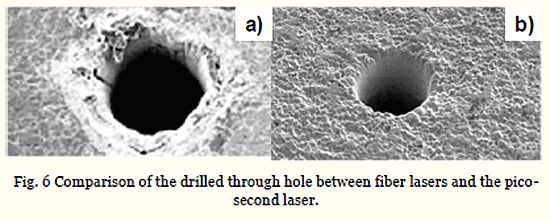
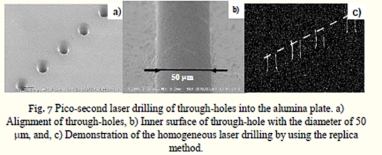
No residuals or no redeposits at the vicinity of through-hole inlets prove that the present pico-second lase drilling is free from the thermal effects to deteriorate the surface quality of work specimen. The pico-second laser drilling is utilized to fabricate a series of holes with periodically aligned into alumina substrate. Figure 7 a) depicts the through-holes drilled into the alumina. Each through hole is aligned with the pitch of 300µm as programmed by the CAM data mining through the positioning control of beams. As had been discussed in [11], the inner surface quality of through-holes is sensitive to the instability during the laser drilling. Figure 7 b) also demonstrates that the straight through-hole inner surfaces are formed to have constant diameter without any geometric damages by the pico-second laser drilling. This is because the laser beam is well profiled through the trepanning system before fine control by the galvanometer, and, is controlled to move into the depth of work materials. The above straightforwardness of through holes is also demonstrated by using the replica method. In this method, the silicone-based polymers are infiltrated into each through-hole. The frozen polymers are used as a replica to reproduce the drilled through-hole shape. Figure 7 c) depicts the alignment of replicas in correspondence to a series of laser-drilled through-holes. Three through-holes were laser-drilled down to the same depth in the alumina plate. Since the first three polymer pillars have the same height as 150µm, the successive series of through-holes are accurately machined into the alumina with the same depth.
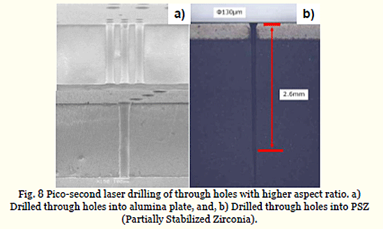
These straight through-holes with high aspect ratio provide a solution to the demand for the probe-cards to make accurate inspection of the semi-conductor chips. The probe-pins are pierced through the straight through-holes of alumina or PSZ substrates for inspection. These through holes must have higher aspect ratio than 10 to preserve the sufficient working space. Figure 8 a) depicts the through-hole with the diameter of 50µm machined into the alumina plate with the thickness of 1mm; the aspect ratio reaches to 20. This high aspect ratio is also attained even when laser drilling PSZ in Fig. 8 b). This demonstrates that the trepanned laser drilling enables to make through-holes with higher aspect ratio than 20 under the well-structured set-up in laser machining.
Micro-drilling into metallic alloys. In the die and mold industries, the case-hardened and plasma treated steels are often utilized for high proof of
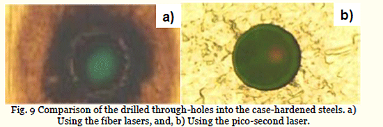
dimensional accuracy. Let us also compare the laser drilling performance between the fiber-lasers and the pico-second laser. Figure 9 compared the drilled through-holes between two lasers. The large heat affected zones as well as damages surround the drilled hole by fiber laser in Fig. 9 a). While, the clean and accurate through hole is drilled into the case-hardened steels by the pico-second laser in Fig. 9 b).
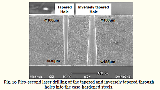
Without use of the beam rotation control, the tapering is difficult or nearly impossible in the laser drilling. In the present set-up, the pair of lenses in the beam rotator in Fig. 5 is radially adjusted to directly control the diameter of irradiated region. When this diameter is narrowed from the inlet to the outlet with the constant velocity, the uniformly tapered through-hole is drilled to have a constant tapered angle up to the specified positive skew angle. On the other hand, the inversely tapered through hole is also machined by enlarging this diameter with the constant velocity in the similar way down to the negative skew angle. This tapering or inversely tapering processes from the inlet to outlet of the through-hole are automatically programmed. After CAM data in the present laser drilling, this diameter of irradiation is narrowed from the inlet by 100µm to the outlet by 30µm with the constant feeding velocity. Then, the tapered through-hole is built into the alumina plate with the constant angle of +30o and the higher aspect ratio than 10.0 in Fig. 10. In the similar way, the inversely tapered through-hole is formed by enlarging the diameter of irradiation from the inlet by 100µm to the outlet by 180µm also with the constant velocity. The inversely tapered through-hole is also drilled into the alumina with the thickness of 1 mm. The inversely tapered angles is also constant by -25o. In both cases, the inner surfaces of holes are finely shaped with less roughness [14].
4. Fine micro-texturing onto metallic alloys and polymers
Micro-textures with the size in the order of 1 to 100µm on the solid surface and interface, work to reduce the friction and wear, to assist the joinability and to functionalize the surfaces and interfaces [15]. Micro-milling [16] and micro-EDM (Electrical Discharge Machining) [17] have been utilized to make micro-texturing onto the steel surfaces. Due to the limitation on the machining tool shape and their controllability for machining, their application is also limited in practice. Short-pulse laser machining is employed to make micro-texturing onto the metallic and ceramic surfaces.
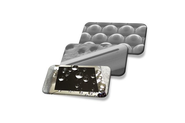
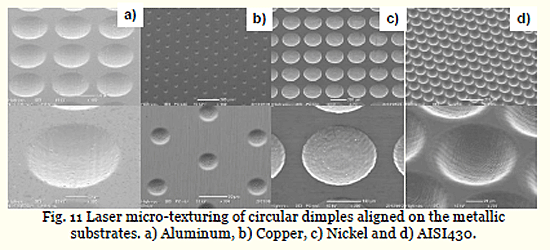
Micro-texturing of dimples onto the surfaces. A circular dimple is formed on the various metallic surfaces as an aligned structure. Figure 11 depicts four micro-texturing cases. The unit-geometry of micro-dimples, their alignment on the surfaces and the finished surface quality are preserved with less roughing during laser processing. For an example, the circular micro-dimples with the diameter of 95µm and the depth of 26µm are formed on the AISI430 surface in the pitch of 110µm as shown in Fig. 11 d). No difference in micro-dimple size and shape and in its alignment is noticed for various kinds of metallic substrates.
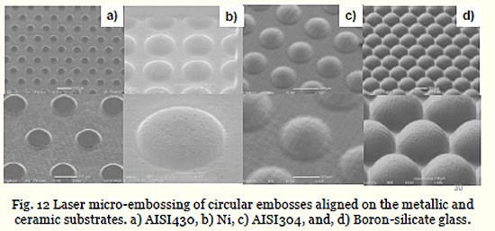
Micro-texturing of embosses onto the surfaces. The initial geometric
data in CAD and CAM for laser micro-dimple texturing is data-transformed from positive to negative; this transformed CAD and CAM data are automatically built for laser micro-emboss formation. In practice, the concave patterning to form the micro-dimples changes itself to the convex patterning to form the microembosses onto the substrate surfaces. Figure 12 depicts four micro-embossing cases. The dimensional and geometric accuracies are preserved in the similar manner of micro-dimple formation. For an example, the circular microembosses with the diameter of 250µm and the depth of 125µm are formed on the boron-silicate glass surface in the pitch of 280µm, as shown in Fig. 12 d).

Micro-texturing of 3D-lattice structures onto the surfaces. With use of femto-second lasers, finer micro-textures are formed as a three dimensional structure on the metallic surfaces. Figure 13 depicts the three-dimensional micro-structures formed on the steel surfaces. In particular, the Gaussianshaped pillar array with the height of 20µm and the pitch of 20 µm is machined into the AISI430 substrate as shown in Fig. 13 c).
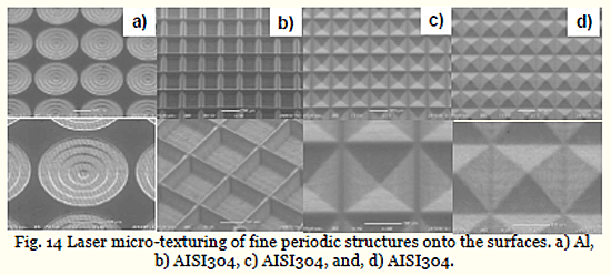
Micro-texturing of periodic structures onto the surfaces. Threedimensional periodic micro-structures have a capability to functionalize the metallic surfaces for optical reflection and diffraction devices and for stamping die and injection mold to transcribe their negative textures onto metallic and polymer sheets. Figure 14 depicts the periodic micro-structures formed on the aluminum and AISI304 steel substrates, respectively. Fig. 14 a) is a stepwise terrace structure machined into aluminum with each layer thickness of 5µm by decreasing the diameter from 450µm down to 50µm with the step of 100µm.


5. Fine micro-texturing into carbon-base molds
Two and three dimensional micro-texturing becomes much important in preparation of mold-dies for mold-stamping of optical elements [18]. The most popular micro-texture is a Fresnel pattern for optical lens; circumferential patterns with steep surfaces must be imprinted onto the surface of substrate materials. V-letter-shaped micro-patterns are laser-machined onto the glassy carbon substrate to discuss the dimensional accuracy and to investigate the depth profile for different aspect ratio. Furthermore, our developing micro-stamping system [19-21] is utilized to duplicate these micro-patterns onto optical polymers by using the patterned glassy carbon mold-dies and to discuss the accuracy by this imprinting.
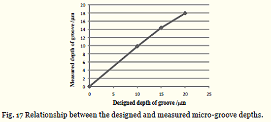
Micro-texturing into glassy carbon die substrate. In the two dimensional microtexturing, a unit pattern like a groove, a dimple, or a wedge is machined with the specified regularity onto the substrate by using X-Y positioning control. Here, a micro-groove is employed as a standard unit pattern to fabricate the microtextured mold-die. Glassy carbon (GC) substrate is employed to make V-letter shaped micro-grooving with the pitch of 35µm, the V-shaped wedge width of 10µm, and the depth of 10 m in design. Figure 15 a) shows the optical micrograph of V-shaped grooving pattern on GC substrate. One groove is laser-machined twice on the same deigned machining-path. This micro-pattern is formed onto the GC substrate with the area of 25 x 25mm2 for 40 minutes or 2.4 ks. As shown in Fig. 15 b), a sharp wedge of micro-groove is imprinted onto the multi-layered GC substrate. The micro-groove has 10µm in width, and 35µm in pitch. The geometric dimensions specified in CAM program are accurately reproduced in the actual laser micro-texturing. The depth profile of V-letter shaped micro-grooves is directly measured to investigate the accuracy of depth in the two-dimensional texturing. Figure 16 depicts the measured depth profile by precise surface profilometer. Deviation of depth ranges from -1µm to +2µm around the average depth of 10µm. This proves that regular patterns could be machined by the present approach. In order to investigate the controllability of micro-grooving in depth, the designed depth-parameter is varied with the laser beam power kept constant. Figure 17 compares the relationship between the designed and measured depths in this micro-grooving. Up to 20µm, the average depth of micro grooves is accurately controlled by the present laser machining system.
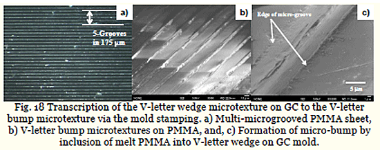
Mold stamping into optical plastics. The above micro-textured GC substrate is used as a mold-die for warm mold-stamping. PMMA sheet with the thickness of 1 mm is employed as a work material for this mold-stamping just above its glass-transition temperature of 383 K (or 110 C). Figure 18 a) showed the V-letter shaped grooving patterns, which are imprinted onto PMMA by the load of 1 kN for 60 s. The V-letter shaped concave patterns in Fig. 15 b) are accurately imprinted onto PMMA as the convex micro-pattern as shown in Fig. 18 b). That is, a series of micro-wedge fins are fabricated by this mold-stamping with use of micro-textured mold in Fig. 15. In the mold-stamping, the filling process of work materials into the micro-patterns on the mold-die is essential for accurate imprinting. Precise observation with higher magnification in SEM is made to investigate this filling behavior at the initial stage of mold-stamping. Figure 18 c) depicted a convex bump with the width of 10µm and the height of 3.5µm. This bump formation is just the initial stage of filling process for viscous PMMA to infiltrate into the V-letter shaped groove by mold-stamping. In case of mold-stamping just above the glass transition temperature, viscosity of plastic materials is so high as to reduce the filling velocity. This reflects on the slow shearing along the side faces of micro-groove.
6. Micro-joining of dissimilar polymers by laser microtexturing
Most of mobile cellular phones are not water-proven so as to be diminished in the accident where those were dropped into water. To be free from these damages, there have been done many efforts to install the perfect water-proof into them [22]; e.g., a silicone rubber ring was sandwiched between plastic cover cases to prevent from water penetration through clearance. This fixture might work well just after shipping; it could be useless at the presence of dirt on the interface or through its misalignment by users in daily use of mobile phones. As the first remedy, a liquid silicone rubber with adhesives is fixed onto their polymer case by the liquid injection molding (LIM) process [23]. Since adhesives invoked in the silicone are responsible for joining, delamination might occur in partial after repetitive opening-and-closing operations in daily use of mobile phones. This difficulty requests us to reconsider the joining process between flexible rubber and hard plastic case in the mobile phone.
The microgrooves are formed into the stainless steel mold for injection molding [24, 25]. Silicone rubber is joined with the polycarbonate plate as a specimen for joining strength test. The measured joining strength is constant by 4 N/mm at the presence of fine microgrooves, where the thinnest silicon rubber fractures without interfacial delamination. This joinability is common to the mobile phone model. The water proof testing demonstrates that this joined interface has sufficient integrity at high pressure state by 15 kPa.
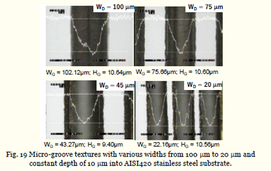
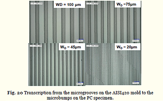
Micro-grooving into the mold for injection molding. The pico-second laser microtexturing with use of the galvanometer is employed to form the microgroove textures onto the AISI martensitic stainless steel mold. Figure 19 depicts four micro-grooved AISI420 molds with varying widths of 100, 75, 45 and 20µm, respectively. The groove depth is constant by 10µm. Each microgroove is shaped to have Gaussian profile irrespectively; the beam intensity profile directly reflects on this microgroove geometry. This mold is inserted into the dieset for injection molding. Polycarbonate (PC) is employed as a work material to imprint these microgroove textures onto the work surface. Figure 20 depicts the transcribed micro-bump textures onto PC from the icrogroove on the AISI420 mold. Both the groove width and pitch are accurately preserved through this injection molding.
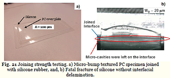
Joining strength test. In the LIM process, adhesive primer is deposited onto the interface before infiltration of silicone melt in the mold-die. Since
intermission between two processes is less than 2-3 seconds, adhesion takes place between silicon and PC-plate under the cooling stage. Figure 21 a) depicts the PC plate specimen with a silicone square ring after joining in the inside of mold-die during LIM process. In the following test, only the joined section in the width of 80 mm is used for tensile adhesive strength testing. A uniaxial tensile testing system with the dynamic video monitoring is used to measure the loading behavior till the final fracture with insitu observation on the deformation of silicone. As shown in Fig. 21 b), when the microgroove width is less than the intrinsic micro-cavity width of 100µm, the fatal fracture occurs in the tensile silicone rubber without any delamination of interface between PC and silicone. This joining strength reaches 4 N/mm irrespective of the joined length and size even if the micro-cavities are present on the interface. This implies that microtextures on the joined interface could control the cavitation process to be free from interfacial delamination.
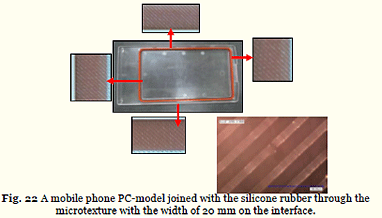
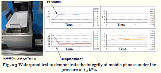
Water-proof test of cellular-phone model. The skewed microgrooves with their width and depth of 20µm are laser-machined into the AISI420 die insert. In the similar way to preparation for the PC-specimen with the silicone rubber ring, the injection molding is used to transcribe the microgrooves into the PC-cover case; LIM process is also utilized to make insitu joining of silicone rubber ring onto the PC-cover case via the micro-bump textures on PC. Figure 22 depicts the mobile phone model, fabricated in the above procedure. Each interface between the PC-cover case and silicone rubber has microbump textures. The Hamron leakage testing is employed to perform the water proof test; e.g., this test aims at the quality check of significant deformation by small leaks under the applied pressure for 5 mins. This model is dipped into a water pool, pressurized up to 15 kPa and held for 5 mins. As shown in Fig. 23, the PC-cover case deforms by pressuring it up to 15 kPa; no further deformation is detected during the holding duration. This demonstrates the perfect water-proof on the jointed interface with aid of microbump textures.
7. Surface property control by laser nano-/micro-texturing
Super-hydrophilicity and super-hydrophobicity have grown up as a key surface engineering to keep clean and fresh surface of products and to control the liquid flow on the product surfaces. The oxide-glass lens as well as metallic-glass, optical elements are a typical targeting product to have their surface hydrophilic or super-hydrophilic for liquid film formation, and to have it hydrophobic or super-hydrophobic for well-defined water repellency [26]. The high energy surface had higher attractice capapcity to other material atoms and molecules; those are adherent to each other to form a wet film on the surface. While, the low energy surface had lower attractive capacity to other material atoms and molecules; those are isolated from each other to form the droplets on the surface.
There are two modofications to control this surface state; e.g., the chemical and physical treatments. The chemical treatment is a general tool to modify the surface condition; e.g., floruine based coating increases the contact angle up to 130o to 150o in [27]. On the other hand, the idea of lotus effect has been discussed as an physicl approach to form hydrophobic surface [28]. This lotus effect works in nature since the water droplets are supported by the air gap through the fine fibrous lotus leaf; this idea suggests that wettability might be widely controlled by the micro-/nano-texturing [29]. As has been reported in [30-32], the femto-second laser micro-/nano-texturing methods have been developed to tune the surface wettability from super-hydrophilic to super-hydrophpbic states. In particular, the micro-/sub-micro textures are formed on any materials by the laser induced periodic surface structuring (LIPSS), where the incident and refelected lights have interaction with the scattered and defracted lights at the vicity of surface roughness [33]. Among several aproaches to design this LIPSS, the authors proposed the micro-/sub-micro texturing design by LIPSS with use the fundamental wavelets and high frequency ripples [34-35]. Here, LIPSS is formed onto the AISI304 stainless steel substrates by using the femto-second laser texturing. Both the super-hydrophilic and super–hydrophobic surfaces can be formed by the present laser nano-/micro-texturing. The geometric effect of surface geometry on the super-hydrophobicity is discussed to optimize the laser surface profile control.
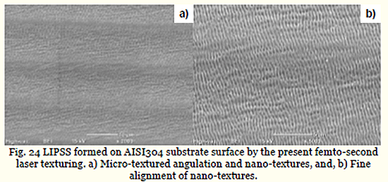
LIPSS by femto-second laser texturing. With reduction of the pulse duration, the optical interaction with irradiated materials localizes in the wave length range. When irradiating the materials in the fundamental mode, this interaction field is limited within the sub-micrometer range. LIPSS is a typical local interaction, occurring at the site of material surface roughness in the order of µm. Figure 24 depicts the LIPSS formed on the austenitic stainless steel type 304 by the present femto-second laser texturing. Nanotexturing alignment angulates itself across the microtexture in Fig. 24 a) since optical interaction is affected by the surface profile in m range. As shown in Fig. 24 b), the spatial periodicity of these nanotextures is constant by 250 nm. This reveals that fine nanotextures with constant periodicity are formed on the metallic surface by the femto-second laser treatment.
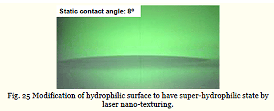
Super-hydrophilic surface formation. After the classical theory on the surface wettability [36], the hydrophilic or the hydrophobic surfaces are modified to have super-hydrophilic or super-hydrophobic states, respectively. This is because the geometric item works to decrease the contact angle for hydrophilic surface or to increase it for hydrophobic one. Figure 25 depicts the wettability of nano-textured AISI304 surface by the femto-second laser surface modification. The measured contact angle reaches down to 8o; it is super-hydrophilic. This reveals that the classical theory is true to describe the geometric nanotexture effect on the contact angle when the spatial periodicity of nanotextures work as a major geometric item in surface quality.
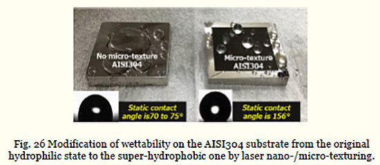
Super-hydrophobic surface formation. In addition to the nano-texturing surface modification, the micro-texturing angulation is taken into account as the geometric item. AISI304 stainless steel sheets with the size of 25 x 25 x 3 mm3 are nano-/micro-textured to investigate the change of surface wettability by this processing. Fig. 26 compares the droplets swelling on the specimen before and after this micro/sub-micro laser texturing. The contact angle of pure water on the bare stainless steels is 70 to 75o, corresponding to the normal wettability of metals [37]. Through the present texturing, the contact angle increases up to 156o. This proves that nano-/micro-laser texturing provides a tool to modify the wettability of stainless steel surfaces from hydrophobic to super-hydrophobic state. This finding is completely against the classical theory; if more geometric items are put into laser texturing, the material surface quality can be widely controlled by geometric design.
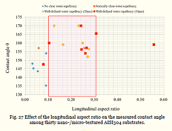
Optimization of surface geometric configuration. There are two geometric items affecting on the surface property; the fractal dimension and the aspect ratio for nano-textures [38]. The former influences on the complexity of surface geometry; the latter, on the local angulation of geometry. Thirty AISI304 stainless steel sheets with the size of 10 x 10 x 0.1t mm3 are laser nano-/microtextured to investigate the effect of micro-texture pitch and height on the measured wettability. Figure 27 describes the relationship between the aspect ratio of nanotexture width to height on the measured contact angle. When this aspect ratio is less than 0.1 or more than 0.3, almost all measured contact angles are less than 155o; the micro-/sub-micro textured AISI304 specimens are only hydrophobic. Higher contact angle up to 170o is attained when tuning this aspect ratio between 0.2 and 0.3; e. g., when using the micro-textures with the width of 20µm, their height might well be 2 to 6µm. This implies that local angulation of surface geometry has significant influence on the controllability of hydrophobicity.
8. Friction control of tools by laser micro-texturing
Under the strong demand for reduction of environmental burdens in manufacturing, every productive line must be energy-saving and highly materialefficient with less emission to environments [39]. In past, the huge amount of lubricating oils has been utilized to reduce the friction and wear not only in automobile industries but also in machining, metal forming and so on [40]. In order to reduce this amount down to the minimum quantity, the contact surface of mechanical parts and tool surfaces are micro-textured to reduce the friction coefficient and wear rate under minimum quantity lubrication (MQL) [41]. Micro-dimples on the working interfaces and surfaces play as a lubricating oil pocket to form a thin lubricating oil film on the interface between sliding parts and between work materials and tools [42]. The depth profile of each microdimple reflects on the local pressure distribution; this interfacial lubricating film works as a pressure boundary to support the sufficient film thickness to lubrication under MQL [43]. In addition, these micro-dimples work as a reservoir to store the wear debris of work materials and tool chips during the semi-dry machining and metal forming [44]. Here, the micro-dimples are formed by the pico-second laser texturing onto the dies and tools. The pin-onball method is employed to evaluate on the reduction of friction for the microdimpled die. The normal milling test is also utilized to describe the effect of micro-dimpled cutting tool on the reduction of tool wear.
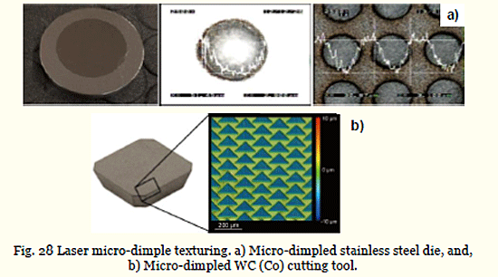
Lase micro-texturing of dimples. The pico-second laser micro-texturing is employed to form the circular micro-dimples onto the AISI420 stainless steel dies, with the diameter of 50 and 100µm and the depth of 10µm in the regular lattice alignment with the pitch of 100 and 200µm, respectively for tribotesting. While, the isosceles triangular micro-dimples with the bottom edge of 155µm, the height of 80µm and the depth of 5µm are machined onto the WC (Co) cutting tools in the zigzag alignment. Figure 28 depicts these micro-dimpled specimen and tool together with the SEM-image and three dimensional profile of micro-dimples.
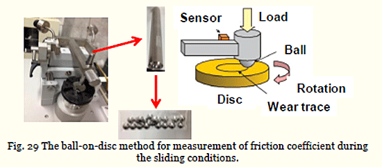
Tribotesting. The pin-on-ball testing is employed to measure the time evolution of frictional force under the constant normal load. In this testing, the counter material ball is on contact with the die material under the applied normal weight as depicted in Fig. 29. The frictional force is directly measured by load sensor attached to the arm. In the following tests, SUJ2 hard balls are utilized as a counter material. The friction coefficient is calculated by division of the measured friction force to the applied normal load. Figure 30 depicts the transients of friction coefficient with increasing the sliding distance for three die specimens; e.g., a bare AISI420 die without micro-dimples, and, two micro-dimpled dies with the micro-dimple diameter (D) of 100µm and its pitch (p) of 200µm and with D = 50µm and p = 100µm, respectively. In case of bare die, the friction coefficient increases monotonically with sliding distance up to 0.15. When using the micro-dimpled die with D = 50µm and p = 100µm, lower friction coefficient than 0.07 is preserved during this tribotesting.

Machining test. When milling the aluminum alloys by WC (Co) tools, the tool face is inevitably subjected to adhesion of work material. Micro-texturing into the tool face enables to reduce this adhesion by storing the wear debris and cutting chips into these pockets on it. In this experiment, AA5052 aluminum alloy is employed as a work material for normal milling with use of the bare WC (Co) and micro-textured one as shown in Fig. 28 b). Figure 31 compares the adhesion process of work material onto the tool face at the milling distance (L) of 900 and 1800 m, respectively between the bare and micro-dimpled tools. Without micro-dimples, the adhesive area and thickness of work materials onto the tool face enlarges with increasing L; e.g., when L = 1800 m, nearly the whole face is covered by these work adhesives with their film thickness of 10µm around the tool edge. On the other hand, little adhesion to micro-dimpled face is noted even after milling up to 1800 m. This significant reduction of adhesion by microtexturing comes from the storing mechanism where the wear debris and cutting chips are reserved into each micro-dimple. This reduction of adhesion influences on the cutting force; e.g., the cutting force becomes relatively insensitive to cutting distance when using this micro-textured tools.

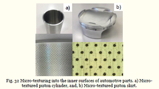
Applications. Low friction and wear is indispensable for most of automotive parts and manufacturing tools. They have curved surfaces, the friction coefficient of which must be reduced to save the energy waste and to improve the fuel efficiency. In particular, the piston cylinder as well as piston skirt are important sliding-part. Figure 32 a) shows the micro-dimpled AISI316L inner surface of cylinder with the size of 30 x 500µm2 and the depth of 5µm in the pitch of 1 mm in the circumferential direction and 0.5 mm along the length. This wedge-shaped micro dimples improve the fuel efficiency significantly. The AA7075 piston skirt is also micro-dimpled to have circular dimples with the diameter of 30µm, the depth of 3µm and the pitch of 120µm, respectively, as shown in Fig. 32 b).
9. Discussion
The spatial resolution in this laser machining is first discussed to find out the way to improve its dimensional accuracy. Through the practical survey on the micro-machining and texturing into curved surfaces, the feasible applications are understood to search for the Spatial resolution in laser micro-machining. Laser drilling of circular holes is employed as a benchmark test to discuss the dimensional accuracy of 25 x 25 holes in square structure with the diameter of 30 mm and the pitch of 50mm, as depicted in Fig. 33 a). Silicon nitride plate with the thickness of 125 mm is used as a work material. Figures 33 b) and c) shows the X- and Y-deviation maps at the inlet diameter and outlet diameter for 625 holes. Since both maps are nearly coincident to each other, the straightness and circularity is preserved to be within 1µm/125µm ~ 0.7o, and, within 2µm, respectively. The spatial resolution of hole diameter is within 2.5µm in the 2-reliability.

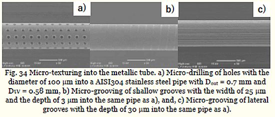
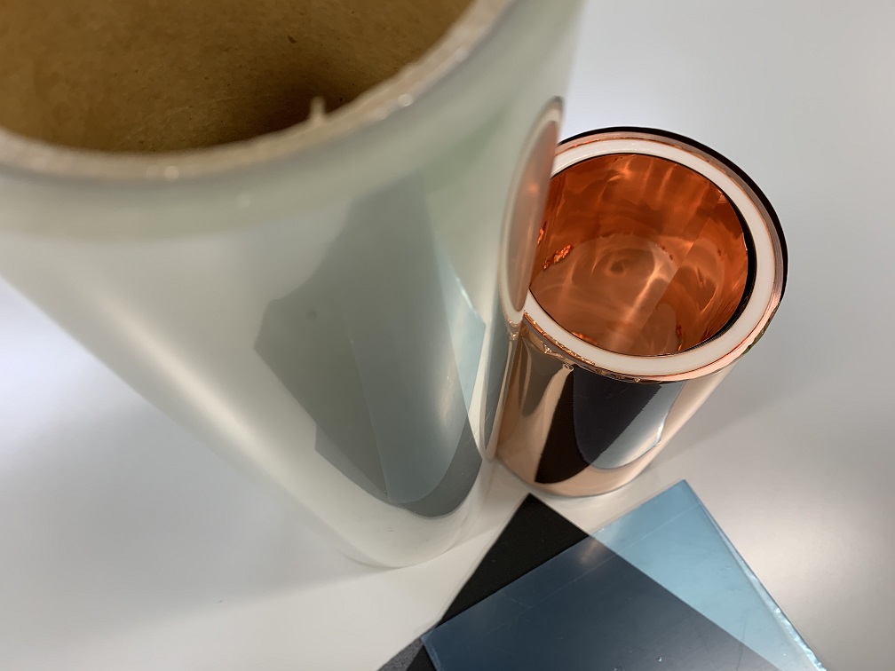
Laser micro-machining into curved surfaces. Without specially designed jigs and fixtures, both the micro-milling and micro-EDM is difficult or nearly impossible to micro-drill the holes and grooves. Laser micro-drilling has little constraint in the manufacturing set-up; it is readily applied to make direct drilling. AISI304 stainless steel pipe with its outer diameter (Dout) of 0.7 mm and its inner diameter (Din) of 0.58 mm is employed as a work to make micro-drilling the holes and grooves. Figure 34 shows three micro-texturing cases; e.g., a micro-drilled pipe, a spiral-grooved pipe, and, a laterally grooved pipe. The deigned textures can be accommodated to the curved surfaces by this laser microdrilling.
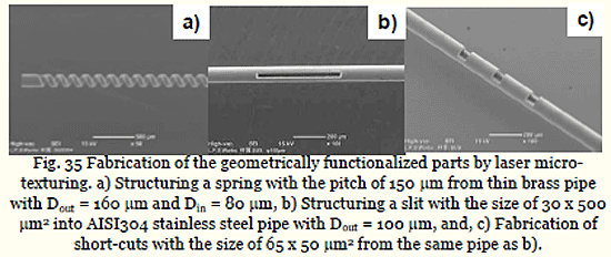
Another feature of laser micro-texturing is developed by changing the beam control. A thin spring is structured from a pipe in Fig. 35 a). A wide slit is structured into a pipe as depicted in Fig. 35 b). Any shaped short-cuts are equipped into a pipe as shown in Fig. 35 c). This suggests that complex microstructure can be built in the micro-machine and micro-member.
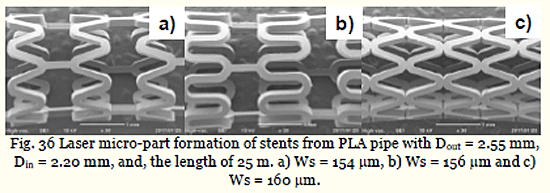
Laser micro-part formation from pipes. Let us discuss how to make laser-structuring a micro-part from commercial components. A polylactic acid (PLA) pipe is employed as a starting component to fabricate the PLA-stents for medical usage. Figure 35 depicts three PLA-stents fabricated from the same PLA-pipe by the laser micro-texturing. These three can be selectively made from PLA-pipe only by varying the slit width (Ws) to be 154 mm, 156mm and 160 mm, respectively. The topological geometry of stents can be designed and fabricated for each medical treatment by tuning the laser micro-texturing parameters.
Future trends in laser micro-manufacturing. Various geometric transformation can be realized only by the laser processing such as the micromachining, micro-texturing and micro-structuring in the above. Through the fusion of other manufacturing treatments with the laser processing, further advancement is expected to propose the innovative procedures. With combination of laser nano-/micro-texturing with laser polishing, the surface property is selectively controlled to be super-hydrophilic or super-hydrophobic by tuning the LIPSS-conditions. With combination of laser micro-texturing with the mechanical milling, a multi-material part as well as a structural member with large area can be functionalized as a complex-shaped part or as a functionalized component.
Among the engineering issues related to ultrashort pulse laser processing, how to put the fast-rate micro-texturing into practice is one of the important targets. In addition to increase of repetition frequency in laser oscillation, new optical control must be developed to transform the spatial geometry and topology in shape into time sequence of scanning in beam technology.
10. Conclusion
The pico-second and femto-second laser processing is designed to be tools for advanced manufacturing; laser micro-drilling, laser micro-texturing, laser nano-/micro-texturing, laser micro-structuring and so on. The dimensional accuracy, the spatial resolution as well as the circularity approaches to 1µm or less than; every micro-part, every micro-structure and every micro-texture is fabricated in the product size of 10 to 100µm range. Most of engineering issues related to surface and interface are well-defined in this laser processing to find an optimum solution to each problem. Reduction of friction and wear in tools and works is attained by micro-texturing onto the tool and part surfaces. Reliable joining between dissimilar materials and parts is put into practice by chemical adhesion with aid of micro-textures on their interface. Surface and interface properties are also controllable by optimization of nano-/micro-textures.
Sustainable manufacturing requires for the well-designed processing to support the efficient circulation of products, parts and materials in addition to recycle and reuse of second hands. Laser micro-machining is useful to prolong the tool life, to revise the product surfaces and interfaces for multiple use and to assist the multi-materialization for second-hand products and parts.
Further research and development on the unknown features of laser processing is necessary to advance new steps in innovative technology and medical engineering to further improve the sustainability in future society.
Acknowledgments
The authors would like to express their gratitude to Mr. T. Hasegawa, T. Miyagawa (SIT), Dr. K. Wasa (TecDia, Co. Ltd.), Mr. T. Omata and Mr. K. Sanbongi (LPS-works, Co. Ltd.) for their help in experiments. The present study was financially support in part by the METI with Supporting-Industry Projects in Japanese Government from 2010 to 2017.
Conflict of Interest
The authors declared no conflict of interest.
References
[1] Avanish, D., Laser beam machining – A review. Int. J. Machine Tools and Manufacture 2008;48: 609–628.
[2] Davim, P., Nontraditional machining processes: research advances. Springer 2013.
[3] Schmid, K., Manufacturing Processes for Engineering Materials (5 ed.). Prentice Hall 2008.
[4] Aizawa, T., Iohara, T., Japan Patent. 2011-212046. 2011.
[5] Gaertner, E., Polise, V., Tagliaferri, F., Palumno, B., Laser micro machining of alumina by a picosecond laser. JLMN-J. Laser Micro/Nanoengineering 2018;13: 76-84.
[6] Amer, M. S., Ei-Ashry, M. A., Dosser, L. R., Hix, K. E., Maguire, J. F., Irwin, B., Femtosecond bversus nanosecond laser machining: comparison of induced stresses and structural changes in silicon wafers. Applied Surface Science 2005;242: 162-167.
[7] Nasrollahi, V., Penchev, P., Dimov, S.S.: A new laser drilling method for producing high aspect ratio micro holes. Proc. 11th 4M Conf. 2016; 15-18.
[8] Aizawa, T., Inohara, T. Micro-texturing onto glassy carbon substrates by multi-axially controlled pico-second laser machining. Proc. 7th ICOMM 2012; 66-73.
[9] Aizawa, T., Inohara, T. Multi-dimensional micro-patterning onto ceramics by pico-second laser machining. Res. Rep. Shibaura Institute of Technology. 2012;56-1:17-26.
[10] Tokura, K. Machining process. Japanese Textbook for Mechanical Engineering. Japan Society of Mechanical Engineers 2006; 5:111.
[11] Doering, S., Richter, S., Molte, S., Tuennermann, A. In-situ observation of the hole formation during deep drilling with ultra-short pulses. Proc. SPIE 7925 2011; 792517:1-8.
[12] Doering, S., Richter, S., Nolte, S., Tuennermann, A. In-situ imaging of hole shape evolution in ultra-short pulse drilling. Optics Express 2010; 18:20395-20400.
[13] Ashkenasi, D., Mueller, N., Kaszemeikat, T., Illing, G. Advanced laser micro machining using a novel trepanning system. JLMN-J. Laser Micro/Nano-engineering 2011;6 (1):1-5.
[14] Aizawa, T., Inohara, T. Pico-second laser drilling of high-aspect ratio through-holes with and without tapering. Proc. 1st WCMNM 2017; 103:1-2.
[15] Aizawa, T., Wasa, K., Tamagaki, H., A DLC-punch array to fabricate the micro-textured aluminum sheet for boiling heat transfer control. micromachines. 2018;9: 147-1 – 10.
[16] Denkena, B., Koehler, J., Kaestner, J. Efficient machining of micro-dimples for friction reduction. Proc. 7th ICOMM. 2012: 85-89.
[17] Jiang, Y., Zhao, W. S., Kang, X. M., Gu, L., Adaptive control for micro-hole EDM process with wavelet transform detecting method, Proc. 6th ICOMM. 2011: 207-211.
[18] Aizawa, T., Fukuda, T., Oxygen plasma etching of diamond-like carbon coated mold-die for micro-texturing. Surf. Coat. Technol. 2013;215: 364-368.
[19] Aizawa, T., Itoh, K., Inohara, T., Imprinting of patterns onto polymers and oxide-glasses via fine micro-stamping. Proc. 6th ICOMM 2010:77-82.
[20] Aizawa, T., Inohara, T., Micro-texturing onto glassy carbon substrates by multi-axially controlled pico-second laser machining. Proc. 7th ICOMM 2012:66-73.
[21] Aizawa, T., Micro-texturing onto amorphous carbon materials as a mold-die for micro-forming. Applied Mechanics and Materials. 2013;289: 23-37.
[22] Balden, A., Adhesively bonded joints and repairs in metallic alloy, polymers and composite materials: adhesives, adhesion theories and surface pretreatment. J. Materials Science 2004; 39: 1-49.
[23] http://www.shinetsu.co.jp/ (30, November, 2018).
[24] Aizawa, T., Satoh, S., Yamaguchi, T., Micro-texturing design for joining between polymer components. Proc. 9th ICOMM 2014;15: 1-8.
[25] Aizawa, T., Satoh, S., Yamaguchi, T., Joining of polymer systems by micro-texturing toward perfect water-proof. Res. Rep. Shibaura 2014;58: 1-10.
[26] Packham, D. E., Surface energy, surface topography and adhesion. International Journal of Adhesion & Adhesives, 2003;23:437–448.
[27] Nakamae, K., How to form the hydrophobic and super-hydrophobic surfaces in industries, Industrial Materials, 1996;44:26–30.
[28] Cheng, Y. T., Rodak, D. E., Is the lotus leaf superhydrophobic? Applied Physics Letters, 2005;86: 144101.
[29] Aizawa, T., Micro-texturing for tribology and surface engineering in manufacturing processes, Proceedings ISAST IV, 2016: 1-16.
[30] Hoehm, S., Rosenfeld, A., Krueger, J., Bonse, J., Femtosecond laser-induced periodic surface structures on silica, Journal Applied Physics, 2012;1121: 0149010–0149019.
[31] Orazi, L., Gnilitskyi, I., Serro, A. P., Laser nanopatterning for wettability applications, Journal of micro-and nano-manufacturing, 2017;5:0210081–021008-8.
[32] Kietziga, A. M., Mirvakilia, M. N., Kamalb, S., Englezosa, P., Hatzikiriakos, S. G., Laser-patterned super-hydrophobic pure metallic substrates: cassie to wenzel wetting transitions, Journal of Adhesion Science and Technology, 2011;25:2789–2809.
[33] Gečys, P., Vinčiūnas, A., Gedvilas, M., Kasparaitis, A., Lazdinas, R., Račiukaitis, G., Ripple formation by femtosecond laser pulses for enhanced absorptance of stainless steel, JLMN-Journal of Laser Micro/Nanoengineering, 2015;10:129–133.
[34] Hasegawa, T., Aizawa, T., Inohara, T., Wasa, K., Fabrication and control of super-hydrophobic surfaces by the femto-second laser machining, Proc. 1st World Congress on Micro and Nano Manufacturing, 2017:381–382.
[35] Hasegawa, T., Aizawa, T., Inohara, T., Wasa, K., Engineering design for super-hydrophobic surfaces via the femto-second laser machining, Proc. 10th Asian Workshop on Micro/Nano Forming Technology, 2017:33-34.
[36] Kawase, T., Super-hydrophobic surface, SEM’I GAKKAI, 2009;65:200–207.
[37] Kam, D.H., Bhattacharya, S., Mazumder, J., Control of the wetting properties of an AISI 316L stainless steel surface by femtosecond laser induced surface modification, Journal of micromechanics and microengineering, 22 (2012) 105019-1–105019-6.
[38] Hasegawa, T., Aizawa, T., Inohara, T., Wasa, K., Hot mold stamping of optical plastics and glasses with transcription of super-hydrophobic surfaces. Procedia Manufacturing, 2018;13:1437-1444.
[39] Allwood, J. M., Cullen, J.M., Sustainable materials. UIT 2012.
[40] Kataoka, S., Influence of lubricants on global environment. J. Jpn. Soc. Technol. Plast. 2005;46: 4-10.
[41] Czichos, H., Habig, K.-H., Tribologie-Handbuch (Tribology handbook). 2nd Ed., Vieweg Verlag, Wiesbaden 2003.
[42] Aizawa, T., Morita, H., Dry progressive stamping of copper-alloy snaps by the plasma nitrided punches. Mater. Sci. Forum. 2018;920: 28-33.
[43] Aizawa, T., Morita, H., Tribological design and engineering in surface treatment for semi-dry and dry stamping. Proc. ICTMP 2016: 14-28.
[44] Sugihara, T., Enomoto, T., Performance of cutting tools with dimple textured surfaces: comparative study of different texture patterns. J. Int. Soc. Precision Engineering Nanotechnology. 2-17:49; 52-60.